| Back to Back Issues Page | ||||||||||||||||||||||
 |
||||||||||||||||||||||
|
PWL#126 - SAW Flux, Fitting Alignment, Alternatives to Hardfacing, Cold Spray for Repair, New Parts February 03, 2014 |
||||||||||||||||||||||
| We hope you will find this Letter interesting and useful. Let us know what you think of it.
PWL#126
Submerged Arc Welding Fluxes - A Primer (Part 1), Fitting Alignment, Powder Metallurgy and Hot Isostatic Pressing (PM/HIP) process for application of wear-resistant hardfacing materials (in alternative to welding), GE advances Cold Spray for Repair and Building of Parts, Weld Preheating, Bulletin_92, Understanding Advancements in GMAW Control and much more...
February 2014 - Practical Welding Letter - Issue No.126
DON'T USE REPLY to send your messages! Use
the Contact Us form instead.
This publication brings to the readers practical answers to welding problems in an informal setting designed to be helpful and informative. We actively seek feedback to make it ever more useful and up to date. We encourage you to comment and to contribute your experience, if you think it may be useful to your fellow readers. You are urged to pass-along this publication to your friends, if you like it, and if you think it may help them. If you received this from a friend and if you like what you read, please subscribe free of charge and you will also receive a bonus book on Practical HARDNESS TESTING Made Simple. The addresses reported hereafter were live and correct at the time of their publication. There is no guarantee that they will always be so, because they are administered by the sources themselves and are under their control. Note: References to articles or other documents are given here in If they are URL's (Uniform Resource Locator), which is the analogue of an address, they begin with "http://..." or "www.". These are not live and must be copied and pasted entirely into the browser (after having been selected with the mouse or otherwise). If they are long they may be displayed in two or more lines. In that case one has to care that the URL be copied completely in a single line without any space, and Enter. If the information is important to you as we hope, you may save the selected pages in a suitable folder on your Computer for easy reference. You are welcome to forward this page to those of your friends who may profit of this information.
(Sponsored Links)
1 - Introduction 2 - Article - Submerged Arc Welding Fluxes - A Primer (Part 1) 3 - How to do it well: Fitting Alignment 4 - Filler Metal Alternatives to Welding Hardfacing 5 - Online Press: recent Welding related Articles 6 - Terms and Definitions Reminder 7 - Article: GE advances Cold Spray for Repair and Building of Parts 8 - Site Updating: Weld Preheating (R), Bulletin_92 9 - Short Items 10 - Explorations: beyond the Welder 11 - Contributions: Understanding Advancements in GMAW Control 12 - Testimonials 13 - Correspondence: a few Comments 14 - Bulletin Board
2 - Article -
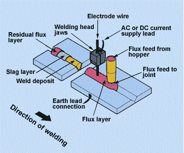
Submerged Arc Welding Fluxes - |
 |
http://www.twi-global.com/technical-knowledge/job-knowledge/submerged-arc-welding-process-005/]
by Naddir M. Patel
http://www.rayatechnicalservices.com/
A Submerged Arc Welding flux is a granular, non-conductive fusible ceramic mixture, manufactured by mixing mineral and chemical components according to various formulations.
Those may include Al2O3, CaO, MgO, MnO, SiO2, TiO2 and CaF2 and sometimes alloy components such as ferro-alloys in proprietary proportions.
The purpose of the flux, covering the weld area, is to shield the weld pool from the atmosphere by physically covering the molten weld metal to prevent arc radiation, sparks, spatter and fumes from escaping.
For manufacturing, this mixture is either fused (melted) in a furnace or granulated-agglomerated using a binder.
Drying and/or sintering are generally accomplished in a rotary kiln and the final product is crushed and sieved to size.
The role of the SAW flux is not just to provide an insulating blanket, shielding the weld zone from the atmosphere, but also to deoxidize and clean the weld metal and act like a scavenger removing any tramp materials within the weld zone.
In a way its function is very similar to steel refining fluxes used in the ladle or mold, only within a very short time frame.
The SAW flux is designed to melt at a temperature just below that of the steel being welded and act like a molecular sieve.
Molecular sieves are used as adsorbent for gases and liquids. Molecules small enough to pass through the pores are adsorbed while larger molecules are not. It is different from a common filter in that it operates on a molecular level and traps the adsorbed substance.
Iron oxides and non-metallic inclusions produced during welding are encased in its complex and proprietary ceramic-refractory structure, and float up to the top as slag, just before the weld metal itself solidifies.
The formulation of the flux thus requires correlation of properties such as melting temperature, fluidity, surface tension, specific gravity and de-oxidation properties.
The flux formulation itself has a critical influence on the shape of the weld bead, on weld metal chemistry and micro-structure and consequently on the mechanical properties.
Unlike the welding wire or electrode, which has a specific chemistry and can be easily classified, SAW fluxes, being mixtures, by definition, cannot be similarly classified.
Nevertheless both American and European standards try to make some order in the matter.
Additional information of fluxes is provided in Annex A6 of the following:
ANSI/AWS A5.17/A5.17M-97(R2007)
Specification for Carbon Steel Electrodes and Fluxes
for Submerged Arc Welding (40 pages)
and
ANSI/AWS A5.23/A5.23M:2007
Specification for Low-Alloy Steel Electrodes and Fluxes
for Submerged Arc Welding (58 pages)
BS EN ISO 14171:2010 is the Specification for Welding consumables:
Solid wire electrodes, tubular cored electrodes and electrode/flux combinations for submerged arc welding of non alloy and fine grain steels.
Fluxes are described in several different ways, including method of manufacture, alloying effect, basicity index and diffusible hydrogen potential.
Based on the method of manufacture, SAW fluxes can be of two types, viz. Fused or Agglomerated. The fused variety is a homogeneous product whose formulation will not change, if fines are generated during handling. As such, weld metal consistency is assured.
As the fusion method of manufacture involves melting the ingredients at temperatures higher than 1300°C, the fluxes manufactured by this method are mostly non-hygroscopic, making them the product of choice in outdoor locations and in applications requiring high impact values uniformly, and consistency in the weld metal.
Agglomerated fluxes on the other hand can be alloyed and can be fine tuned for superior resistance to rusting and mill scale.
They are however, moisture sensitive and fines formed during handling could have a detrimental effect on weld quality.
Because of lower manufacturing temperatures, agglomerated fluxes may contain alloys and high melting compounds.
Submerged Arc Welding Flux Stratification
| Flux Type | Advantages | Disadvantages | Applications |
| Fused Flux |
Chemically
homogenous uniform performance. Formation of fines will not change formulation. Generally non-hygroscopic allowing outdoor use. Except for basic versions, requires minimal pre-heating. |
Higher density. Alloys cannot be added. Poor impact properties except with basic versions. |
Outdoors
and field. Where uniformity of weld chemistry is critical. Marine Hulls. |
| Agglomerated Flux | Alloys and de-oxidizers can be added. Best over rust and mill scale. Lower density. Good weld cover. |
Alloy additions decompose in first run. Fines can compromise uniform performance. Flux recycling requires sophisticated controls. Moisture sensitivity requires regular reheat. |
General to critical applications depending on basicity. |
Use of a Fused flux is great for outdoor applications such as site
joining of water pipelines.
Being of a uniform composition, they not only ensure a very stable and repeatable weld metal, but are also very forgiving of poor handling practices in some shops.
For example if the shop has a procedure for brushing off the excess flux after the weld pass and putting it back in the hopper, it is possible that iron oxides and fused slag would also end up there.
Whereas oversize fused slag can be sieved out, the iron oxides can not.
For users of agglomerated fluxes, this is usually a nightmare situation as they will end up with weld defects whose root cause they are unable to locate and chalk it down to operator error.
The frequency of repair and rework that follows is rarely documented and analyzed, as it is done in the next shift and generally considered as non-avoidable.
To fool proof this situation, the welding engineer can either insist on a fused flux which is more forgiving of this flux handling practice, and/or go in for a flux re-circulation system that has the relevant options, such as sieving and magnetic separation to ensure delivery of a clean product to the next or following weld assembly.
If the flux is agglomerated and active, that is, it contains alloying elements, these options do not work.
If the unused flux is brushed off, it will behave like the hit or miss, characteristic of a recycled-reprocessed flux, that some manufacturers use for non-critical applications.
The only other alternative is for the shop to ensure the use of virgin material every time.
Re-heating of the flux also needs to be considered especially in shops where the flux use is carried over consecutive shifts.
Note: Part 1 of this article ends here. Part 2 is due to be published in the next issue of PWL.
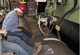 |
[From Advanced New Sub Arc welding Technology...
http://www.lincolnelectric.com/en-us/support/application-stories/pages/gulf-marine-deposition.aspx]
3 - How to do it well: Fitting Alignment
 |
I come back to the practical and informative column of Damian J. Kotecki published regularly by the Welding Journal. I like to quote from that rich repository of useful recommendations because from them we can all learn how to deal with issues showing up in actual manufacturing activities.
In the January 2014 issue of the WJ, at page 20 Kotecki reports on a query he got, relative to the possibility to bring to proper alignment a fitting whose flange was not welded correctly to the cylindrical surface of a 304 tank, because of poor setup.
To correct the orientation of the fitting as required, the welder had suggested to insert a long bar in the fitting, to heat somewhat fitting and tank, and then bend it properly to reach the required direction.
"Is this a good idea?" asked the inquirer. The Author admits that there is some logic in the welder's suggestion, but that the problem is more complex.
In fact if the material is indeed 304 and not 304L, sensitization could have taken place, making the affected material susceptible to intergranular corrosion, if meeting in service a corrosive environment.
For an explanation of sensitization see our page on Stainless Steel Welding.
The Author admonishes that local heating with a flame, being a slower process than welding, promotes sensitization already at 400°C (750°F). To avoid the danger of extending sensitization beyond that due to welding (and deemed acceptable for lack of information) this temperature should no be exceeded.
The Author suggest to use electric strip heaters and to monitor strictly the temperature. He estimates that the yield strength of the material would be reduced by half relative to that at room temperature, and this could help in reaching the wished result.
However, to avoid that the pipe be bent too much, he suggest to put a sleeve (a larger-diameter pipe that just fits over the neck of the fitting) to stiffen the lever arm.
The author concludes that even if the welder's is not a bad idea, its execution is not without risks. Interested Readers are invited to seek the original article pointed at above.
4 - Filler Metal Alternatives to Welding Hardfacing
 |
An article published at page 21 of the January 2014 issue of Advanced Materials and Processes, an ASM International publication, states that the current technology using welding for hardfacing of severely stressed high-performance valve components in the fossil and nuclear power generation industries is challenged by issues associated with some of the welded hardfacing alloys.
Weldability and residual stress challenges are essentially of two types. One, called delamination or disbonding of hardfacing material from ferritic valve seat and disc substrates, brings about failure of valve function and damage to steam turbines.
The other drawback consists in cobalt containing wear debris from hardfaced components finding their way to nuclear reactors, where they are transformed in highly radioactive Co60, that has a half-life of more than five years, and becomes a major hazard for plant personnel working in the surroundings.
This risk is the drive to eliminate cobalt from hardfaced components, by developing wear resistant materials from a wider range of potential alloy solutions not containing this dangerous component.
In particular the application of wear-resistant hardfacing materials using the powder metallurgy and hot isostatic pressing (PM/HIP) process is the object of ongoing research and development at the Electric Power Research Institute (EPRI).
Many difficulties obstruct the path of such development.
There is a lack of uniform, consistent and comparable wear performance data for evaluating hardfacing materials candidates and there is no easy way to assess wear-resistant materials across a wide range of potential wear mechanisms (abrasion, erosion, and galling), and across the range of operational temperatures.
There is a body of experience derived from several decades of acceptable service experience in both (fossil and nuclear) power generation industries, but little comparison data between mainstay hardfacing materials such as Alloy 6 and other materials.
It is also quite difficult to extrapolate lab results from one off tests, made by research initiatives, to real world material and operational behavior.
In fact even the assessment of wear properties tested by accepted ASTM Standards (G98 and G133) are challenged by the discovery that advanced characterization tests, like those by laser confocal microscopy, demonstrate that the older methods provide inconsistent and different results.
Therefore advanced research methods of material characterization are needed, in part applied and described in the article, because examined materials may exhibit either a combination or all of different phases.
In the words of the authors:
"A detailed and predictive understanding of all potential wear mechanisms incorporating fundamental material properties and mechanical behavior, microstructure and part geometries does not exist especially for the
highly varied structures found in some alloy composite systems."
The article recognizes the difficulties in describing the starting microstructure and all successive transformations occurring during galling or sliding wear. The examined materials may exhibit a combination of phase transformations (either by stress or rapid temperature rise at the surface), preferential deformation of phases, strain localization, and/or oxidation.
Hardfacing alloy performance is determined in part by the transition of the wear mechanism during increasing load. Metal alloys in unlubricated sliding contact typically undergo adhesive wear with micron-sized particle formation at low to intermediate loads.
Above a critical load, however, many metals exhibit a transition to galling, with large surface deformations and bonding, accompanied by significant wear debris, high friction, and eventual seizure.
In austenitic hardfacing materials, such as Alloy 6, resistance to galling and sliding wear is a result of a strain-induced martensite phase transformation, which is a consequence of high work hardening at the contact surfaces.
Given the complexity of the matter, the authors think that collaboration among end users, manufacturers, and research organizations must occur. They must unite under the common goal of reaching practical solutions.
Interested readers are urged to seek the article indicated above.
5 - Online Press: recent Welding related Articles
Lincoln Electric Weld Sequencer software
http://newsroom.lincolnelectric.com/News+Releases/new+lincoln+electric+weld+sequencer.htm#.UtviVvuxXcs
How to build a metal cube
FAB.
PWTV: Highlights of FABTECH 2013
www.thefabricator.com/pwtv
Putting a wrap on Schweissen & Schneiden
http://www.thefabricator.com/article/arcwelding/putting-a-wrap-on-schweissen--schneiden
Resistance Spot-Welding Gun Meets Fiber Laser
http://www.photonics.com/Article.aspx?AID=55762
6 - Terms and Definitions Reminder
Lack or fusion or penetration is a nonstandard term for incomplete fusion or penetration.
Misalignment is the amount a joint is out of alignment at the root.
Off Time in resistance welding denotes the time while the electrodes are off the workpieces.
Pressure Controlled Resistance Welding is a resistance welding process variation in which a number of spot or projection welds are made with several electrodes being operated in succession under the control of a pressure sequency device.
Reactor is a device used in arc welding circuits to minimize irregularities in the flow of the welding current.
Shielded Metal Arc Cutting is an arc cutting process that uses a covered electrode
Thermal Gouging is a thermal cutting process variation that removes metal by melting or burning the removed portion to form a bevel or groove.
Weaving is a welding technique where the torch is oscillated transversally as it progresses along the weld path.
7 - Article: GE advances Cold Spray for Repair and Building of Parts
Our readers already know about Cold Spray, a process used for applying coatings of materials with special properties on existing parts.
Extending the idea of 3D printing, this technology, tentatively called "3D painting", has been recently undergoing experimental applications by General Electric (GE) to build new parts and to repair worn or damaged ones.
Metal powders are deposited at high speeds of Mach 4 on the surface of material that needs repair, for example jet plane parts, at temperature below melting point.
The following main points were gathered from GE online publications.
Spray technologies are particularly attractive for the production of large structures, which are challenging for today's powder-bed additive manufacturing processes due to equipment size limitations. The cold spray technique has the potential to scale up to build larger parts, with the only limitation being the size of the area over which metal powders can be applied.
Cold spray demonstrates a unique marriage of materials, process, and product function which can, in the immediate future, transform repair processes for industrial and aircraft components such as rotors, blades, shafts, propellers, and gear boxes.
Since cold spray does not require heat, like common repair processes such as welding, it allows a repaired part to be restored close to its original condition. In GE's Oil and Gas business, GE researchers are exploring cold spray as an alternate way to repair or coat parts involved in oil and gas drilling and turbo machinery.
Cold spray's future benefits include extended product lifespan and reduced manufacturing time and material costs, all of which translate into significant customer benefits.
More information is available at Global Research News at
http://ge.geglobalresearch.com/blog/its-serendipity-cold-spray-leo/
You can watch a GE Cold Spray Technology video at
https://www.youtube.com/watch?v=NXGOZ5ns3Zo&feature=youtu.be.
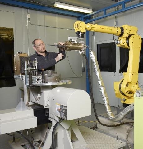 |
to Build Up and Repair Parts
[From http://ge.geglobalresearch.com/blog/its-serendipity-cold-spray-leo/]
8 - Site Updating: Weld Preheating (R), Bulletin_92
The Pages of this Month are a reviewed and updated issue of the Weld Preheating Page, containing a thorough explanations of the reasons why such a process is needed in certain cases and the description of means and controls generally used to perform it.
An additional page has been published at Bulletin 92, with a long list of links to pertinent resources concerning the subject of preheating.
This Bulletin can be reached also through our Welding Resources Page, listing it as Resource 92. This page is regularly updated as new Bulletins are published in the Site.
Readers can get a glimpse of the scope of our website by browsing the Site Map and by jumping, through the links, to the pages that may interest them.
9 - Short Items
Do you know...
Sorry! The source: http://www.industrial-lasers.com/ removed the link. |
9.1 - Blocker is the impression in the dies (or one of a series of impressions in a die set) that gives to the forging an intermediate shape, in preparation to forging to the final shape.
9.2 - Cathode is the negative electrode of an electrolytic cell where reduction is the principal reaction. (Electrons flow toward the cathode in the external circuit.) Typical cathodic processes are cations taking up electrons and being discharged and oxygen being reduced. In electrolytic refining, Copper is deposited at the cathode.
9.3 - Domain, magnetic is a substructure in a ferromagnetic material. In it, all the elementary magnets (electron spins) are held aligned in one direction by interatomic forces. If isolated, a domain would be a saturated permanent magnet.
9.4 - Embrittlement is the severe loss of ductility or toughness or both, of a material, usually a metal or alloy. Many forms of embrittlement can lead to brittle fracture. Thermally induced embrittlement occurs at specific temperatures. Environmental embrittlement occurs by exposure to certain agents like hydrogen embrittlement and stress-corrosion cracking.
9.5 - Flash, in forging, is excess metal extruded from the body of the forging as a thin plate, where upper and lower dies meet. In casting, it is a fin of metal that results from leakage between mating mold surfaces. In friction or upset welding it is the material that is expelled or squeezed out of a weld joint and that forms around the weld.
9.6 - Grinding Fluid is an oil- or water-based fluid introduced into grinding operations
to (1) reduce and transfer heat during grinding, (2) lubricate during chip formation, (3) wash loose chips or swarf from the grinding belt or wheel, and (4) chemically aid the grinding action or machine maintenance.
10 - Explorations: beyond the Welder
Debating the State of Global Science (Video)
SA1.
Why My Parents Have a Closet Full of Lightbulbs
SA2.
Continental Telescope Array Could Usher Astronomy Revolution in Africa
SA3.
Can Fracking Clean China's Air and Slow Climate Change?
SA4.
Why Scientists Should Embrace the Liberal Arts
SA5.
11 - Contributions: Understanding Advancements in GMAW Control
Controlled Gas Metal Arc Welding Processes: an Assessment on Development (14 pages)
www.pm-pipeliner.safan.com/mag/ppl0412/t34.pdf
The publication above intends to examine critically the different control mechanisms used specifically for steering the welding parameters during sensitive welding sequence phases, but excludes from the review those known as GMAW-P (Pulsed Gas Metal Arc Welding).
It is explained that the aim, common to all process variants, is of stabilizing welding conditions in order to increase weld quality and productivity.
As an example, it is asserted that, using a specific control circuit, it becomes feasible to specifically modify the short circuit periods occurring through the weld cycle, achieving process stabilization and spatter reduction.
The author recognizes that the waveform proposed by a currently supplied commercial unit, is essentially identical to that obtained by an old Japanese patent.
To enjoy the advantages of the system while reducing its limitations, additional sensors and hardware need to be permanently connected. Specifically, limiting current levels and source heating dissipation need increased attention.
Applications embedding these principles are currently known as secondary switch controlled welding systems. Welding applications exploiting these, are used especially for thin wall thickness sheet metal joining, but also for root pass welding in pipeline construction, manual and semi-automated.
Another approach, based on applying alternating current, is also based on another quite old Japanese patent. This welding system is based on two inverters. The first controls the absolute value of the output current. The secondary inverter changes the polarity of the output current between electrode positive (EP) and electrode negative (EN).
However arc instabilities were being produced. To address these issues a new filter was introduced, capable of eliminating voltage abnormalities.
The modified process shows considerable advantages. The thermal energy input to the parent material can be reduced by switching the wire electrode from reverse (EP) to straight (EN) polarity.
This leads to greater weld deposition rate, as more filler wire is melted per unit time, and to improved process gap bridging ability due to the reduced heat input in base metal. This process is used successfully in aluminum alloy robotic welding providing stable peripheral conditions with sound weld quality results.
Next the report introduces a different approach combining mechanical and electrical forces for droplet transfer. It is embedded in a commercial application marketed under the brand Cold Metal Transfer (CMT). The principle is based on short circuit metal transfer, but assisted by specific hardware components and advanced software.
The short arc droplet transfer sequence is characterized by arcing and by an extinction period. Moreover, during the arc extinction a characteristic necking sequence caused by surface tension can be observed.
In the CMT process, the detachment from the wire of the molten metal drop in the necking phase, is enhanced by a superposed retracting movement imposed on the wire.
Obviously timing is crucial: the mechanical movement has to be coordinated with the physical condition of the drop and with the electrical parameters (voltage and current).
The article continues by describing several successful applications of this controlled process to different materials, conditions and positions, and enumerates its demonstrated advantages.
Please note that this technology exploits short arc droplet transfer which is applied with reduced current values. It is therefore suitable only for relatively limited thickness dimensions. With higher current values, the metal spray transfer mode takes place, proper for thick sections.
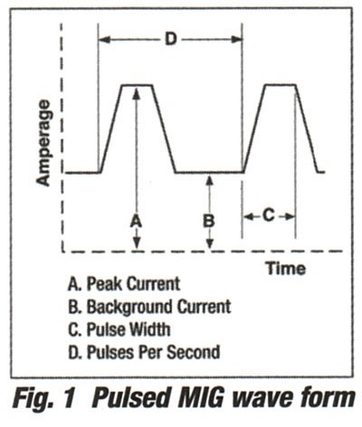
Pulsed spray is a variation of spray transfer in which the welding current is switched from a low background level to a high peak current. The lower average current level allows these settings to be used for thinner material.
This means that for a certain range of thin to moderate thickness, CMT process and pulsed spray may overlap, both providing acceptable weld results.
Although, as usual, we refrain from endorsing or recommending commercial products, we feel that our readers are entitled to get the best updated technical information available, especially if it is likely to increase their productivity.
Therefore readers are invited to read some more information in the following articles. Then they might look for a practical demonstration of the processes promising the most advantages for their application.
CMT welding
Sorry! the link was removed by the Source
www.fronius.com/
New Regulated Metal Deposition (RMD™) MIG Welding Process Improves Stainless Steel Pipe Fabrication
Millerwelds.
Gas Metal Arc Welding Guide (96 pages)
Lincoln Electric.
ESAB - Industrial Equipment
ESAB.
 |
[From: Aluminations (4): Shedding Light on Aluminum Welding Issues
http://www.millerwelds.com/resources/articles/Pulsed-MIG-GMAW-and-aluminum/]
12 - Testimonials
Date: 15 Jan 2014, 05:01:42 AM
Subject: Submission from
Name: Christophe Delaere
E-Mail Address: removed for security
Country: Belgium
Organization: Pressure vessels manufact.
Your Task: Design
Eng.
Details: Dear Elia,
Thanks for the wishes ...
Have a great year 2014 !
Name: Sunil Goyal
E-Mail Address: removed for security
Country: India
Organization: National Engineering Industries Ltd, Jaipur
Your Task: Improve look of robot welding
Details: We have robot welding machine for welding of our large size bearings.[...]
Can you help us?
13 - Correspondence: a few Comments
Following the article published in section 11 above, some further thoughts come to mind.
GMAW is a mature welding process with a long history of successful accomplishments. But the search of the correct set of parameters for any job has often been mysterious for many welders who were not sufficiently instructed or trained.
The development of many kinds of pulse control, while enlarging the fine tuning capabilities of the systems, has been a source of additional confusion for welders who did not profit from adequate training.
The fact that each equipment manufacturer hastens to advertise the commercial brand of their special solution, adds uncertainty to the users, that are unable to compare the products of different suppliers.
I believe that a complete treatise explaining the functions of each control parameter and how to select the best for any job would possibly help to dissipate users' uneasyness and assist them in understanding what they need.
I wonder if it would be possible to build such a fundamental work with knowledgeable readers' help.
Readers able to contribute from their knowledge and expertise are invited to step forward to put together a collective endeavor to be published here for general benefit.
14 - Bulletin Board
14.1 - Energy Conference.
Feb. 5, 6.
Hotel Monteleone, New Orleans
www.aws.org
14.2 - Pipelines Conference.
March 4, 5. Sheraton Houston Brookhollow, Houston, Tex.
www.aws.org
14.3 - FABTECH Canada.
March 18–20. Toronto Congress Centre, Toronto, Ont., Canada.
Cosponsored by the American Welding Society.
www.fabtechcanada.com
14.4 - Stainless Steel Conference.
March 25, 26. Loews Philadelphia Hotel, Philadelphia, Pa.
www.aws.org
14.5 - Weld Cracking Conference.
April 15, 16. Hilton Garden Inn Denver Downtown, Denver, Colo.
www.aws.org

BUILT BY:
Click on this Logo NOW!

Copyright (©) 2014, by Elia E. Levi and
www.welding-advisers.com
All Rights Reserved.
See a short Interview with Ken Evoy
Watch the following video...

See you next time...