| Back to Back Issues Page | |||||||||||||
 |
|||||||||||||
|
PWL#139, Capacitor Discharge Welding, Decarburization Depth, Aluminum Brazing, RSW Adaptive Controls March 02, 2015 |
|||||||||||||
| We hope you will find this Letter interesting and useful. Let us know what you think of it.
PWL#139 PWL#139 - Capacitor Discharge Welding, Measuring Depth of Decarburization, Filler Metal for low temperature Aluminum Brazing, Adaptive Controls for Resistance Seam Welders, Virtual Welding Trainer importance questioned, Casting Repair (NEW) and Resources (NEW) on Casting Repair and much more...
March 2015 - Practical Welding Letter - Issue No.139
Important NoticeThe Mid February 2015 Issue of Practical Welding Letter, Bulletin 105, dealing with online Resources on Casting Repair (NEW), was not distributed by e-mail but it is available at Bulletin 105 and from the updated Welding Resources Page.
DON'T USE REPLY to send your messages! Use the Contact Us form instead.
You are urged to pass-along this publication to your friends, if you like it, and if you think they may enjoy it. The addresses reported hereafter were live and correct at the time of their publication. Note: References to articles or other documents are given here in one of two forms. If they are URL's (Uniform Resource
Locator), which is the analogue of an address, they begin with "http://..." or "www.". If the information is important to you as we hope, you may save the selected pages in a suitable folder on your Computer for easy reference. (Sponsored Links)
1 - Introduction 2 - Article - Capacitor Discharge Welding 3 - How to do it well: Measuring Depth of Decarburization 4 - Filler Metal for Aluminum Brazing 5 - Online Press: recent Welding related Articles 6 - Terms and Definitions Reminder 7 - Article: Adaptive Controls for Resistance Seam Welders 8 - Site Updating: Casting-Repair (NEW) and Bulletin_105 (NEW) 9 - Short Items 10 - Explorations: beyond the Welder 11 - Contributions: Virtual Welding Trainer 12 - Testimonials 13 - Correspondence: a few Comments 14 - Bulletin Board
2 - Article - Capacitor Discharge Welding
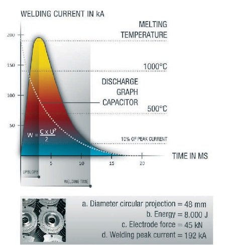
An Article by Nigel Scotchmer, recently published at page 32 of the February 2015 issue of the Welding Journal, provides a useful overview of the advantages of this old process for a number of modern applications. In particular it is recommended for resistance spot welding of light gage sheet metal high strength hot stamped boron steels, recently introduced in the manufacture of automotive vehicles because of their crash resisting robustness. The short time high current capacitor discharge, delivered under high welding force, permits to achieve consistently spot welds of the required strength even as the sheets are coated with a corrosion protective layer of aluminum-silicon, particularly aggressive to the copper alloy electrodes of the welding machine. A spin off of Capacitor Discharge Welding, called Electro Spark Deposition (ESD) is used to add new material in place of worn out layers on the tip of aerospace turbine engine blades. This repair is needed to control clearance between blade and casing, an important operational efficiency parameter. ESD is probably cheaper than both electron beam and laser additive material building. It would be interesting to read some more details and comparative evaluation. The additional comment I got from the author Nigel Scotchmer was: "ESD is lots of fun, (and I like it), but it is tricky. It is just EDM in reverse, really." So we should understand that not all details are open to the public at this stage. ESD is claimed to leave no measurable heat affected zone, with no effect on the finely balanced microstructure of high temperature resistant turbine blades and therefore could be approved for repair. An amazing application reported is that of joining a protective tip of titanium carbide to copper base electrodes of resistance welders. Although a photo is shown in the article, the metallurgy of the joint is not clear. It is possibly a form of braze-welding, as a cermet is not expected to undergo fusion welding. I asked the author Nigel Scotchmer on this subject. His answer: "Well, I would still call it welding. It isn't pure TiC that we use, so it maybe it is that only the other compounds within the sintered TiC cermet that actually weld." The same CD process proved successful for resistance welding of boron steels fasteners with forged projections, with additional benefits of concentrated and short time heating, consisting in avoiding heating of adjacent material so that annealing or deformation are prevented. It is said to be particularly advantageous if the hot stamped and quenched boron steel is coated with Al-Si for corrosion protection. Practical hints are offered in the original article. The process was also approved for field repair of certain components of tanks and submarines. Interested Readers are urged to seek the original article referred to above. More information can be found at the website released by the author, at:
From the quoted article of the Welding Journal, February 2015, page 34
3 - How to do it well: Measuring Depth of Decarburization
An Article, written by George F. Vander Voort, a metallographer of world renown, and published at page 22 in the February 2015 issue of Advanced Materials ad Processes (AM&P), a publication of ASM International, provides the basics for understanding the phenomenon of decarburization and for measuring its actual depth. In the past Issue PWL#105 of this publication for May 2012, an Article on Low Load Hardness Testing reported there in section 7 on an extensive research performed on that subject by the same Author quoted above. The conclusion was that individual measurements of the length of the impression diagonal of indentations used to determine hardness, are affected by personal judgement of different inspectors on the actual focus of indentation edges viewed through an optical microscope. That brings about an unacceptable uncertainty about hardness values, enhancing the need for the development of automatic machine measurements independent of operators. Back to the present subject. Decarburization is a serious problem because surface properties are inferior to core properties, resulting in poor wear resistance and low fatigue life. These are well known consequences of the loss of carbon atoms, occurring mostly when hot steel parts react in furnaces with decarburizing atmospheres. The Author reminds readers that ASTM E1077 describes Standard Test Methods for Estimating the Depth of Decarburization of Steel Specimens.
From the Abstract of this Standard one can learn that:
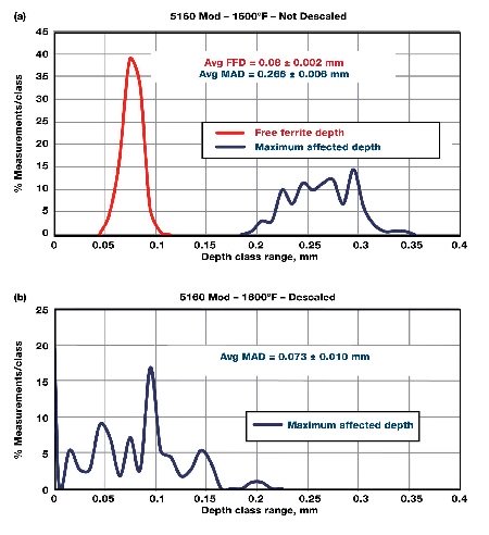
In case of a dispute, the rigorous quantitative or lineal analysis method (see 7.3.5 and 7.3.6) shall be the referee method. These methods can be employed with any cross sectional shape. The chemical analytical methods generally reveal a greater depth of decarburization than the microscopical methods but are limited to certain simple shapes and by availability of equipment. These techniques are generally reserved for research studies. The microindentation hardness method is suitable for accurate measurements of hardened structures with relatively homogeneous microstructures. The Author distinguishes between what appears to be the greatest depth of total carbon loss (free-ferrite depth, or FFD) and the greatest depth of combined FFD and partial loss of carbon to determine the maximum affected depth (MAD). He also explains that the Knoop hardness determined MAD is often somewhat deeper than the visually determined MAD because of difficulties in discerning microstructure variations indicative of different carbon content. The article reports examples of actual results of experimental studies with accompanying micro photographs to illustrate different instances of observed decarburization. In the conclusions the Author stresses the importance of performing correctly the tests and warns that the reproducibility of qualitative measurements that involve personal judgement are not as good as quantitative measurements made on at least 25 randomly selected locations on he affected area. Interested readers are urged to seek the original article reported above to gain better understanding of the problem and to learn how to document adequately the occurrence of decarburization.
Fig. 4 — Frequency histograms of decarburization measurements made around the periphery of 5160 modified bars afer heat treatment. From the quoted article of AM&P, February 2015, page 24
4 - Filler Metal for Aluminum Brazing
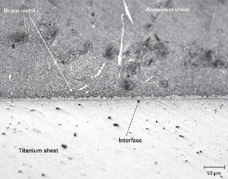
As frequently in the past, the following note reports the article published in the Brazing Q&A Section in the February 2015 issue of the Welding Journal at page 20. In my opinion these thoughtful answers are highly instructive in that they generally tackle the problems at their root, and show how to proceed in the search for a practical solution. A reader looked for guidance as his attempts to vacuum braze Aluminum Alloy 6061-T6 using filler metal BAlSi-4 were met by remelted edges and loss of strength. The Author of the answer, Alexander E. Shapiro, acknowledged that the problem is quite difficult to solve, as "there are still no low-temperature [aluminum] brazing alloys in the United States market appropriate for application in vacuum furnaces". That is, problems may be unavoidable if one has to rely only on BAlSi-4 or BAlSi-3 per AWS A5.8M/A/5.8:2011, Specification for Filler Metals for Brazing and Braze Welding, Table B.2. The first partial solution offered is to repeat after brazing the complete solution treatment for 6061 at 530°C (985°F), followed by rapid water quench (which may cause unacceptable deformation) and then aging at 160°C (320°F) for 18 hours. The disadvantage is additional cost. The alternative is more complex. It consists in preparing a composite filler metal with a foil of BAlSi-4 and one or two foils of pure copper. Readers considering the adoption of this technique would find all the details in the said article. For 6061-T6 flat parts the method is simplified by using only copper foil between the parts. Interestingly, when copper is in contact with aluminum its melting temperature is only 548°C (1019°F), suitable for brazing at 575°C (1067°F). Also in this case complete heat treatment should be repeated to restore useful mechanical properties. The article continues with the introduction of a non standard system based on Al-Si-Ge, considered promising for low temperature vacuum brazing, but to be developed as non standard. Interested readers should seek all the details in the said original article.
Fig. 1 — Macrostructure of aluminum to titanium brazed joint made using composite filler metal TiBraze®Al580 containing BAlSi4 foil 80 microns thick and copper foil 22 microns thick. Brazing temperature 575°C (1067°F) From the quoted article of the Welding Journal, February 2015, page 21
5 - Online Press: recent Welding related Articles Welding Equipment Market 2019 Trend, Size and Growth Analysis Report Guns for Opportunity: Boilermakers union offering welding training in exchange for guns Clearing the air Artistry in metal: 'Making a pretty good living' Fabrisonic Builds Fully Dense, Complex Metal Parts & Heat Exchange[r]s
6 - Terms and Definitions Reminder Arc Braze Welding is a process variation where an electric arc as used as heat source. Blanket Brazing is a process where brazing filler metal preforms are placed in advance in the joints, and heating is provided by flexible resistance heating blankets. Cold Braze Joint is a defect due to insufficient heating resulting in incomplete metallic bonding. Flash coat is a thin layer of brazing filler metal or of a brazing favoring suitable material deposited before brazing on one or both surfaces. Gas generator is equipment that produces a furnace atmosphere Heating Pattern is a description of how the heat source is applied to create a heat pattern for brazing. Joint remelt temperature is that to which a completed brazed joint must be heated to remelt the filler metal and separate the joint. Laser beam brazing uses heat from a laser beam for extremely small joints.
7 - Article: Adaptive Controls for Resistance Seam Welders
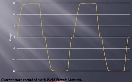
The progress in the capabilities of adaptive controls has achieved the stage where the reaction time required to change parameters in response to measured effects is very fast. An article published in the February 2015 issue of the Welding Journal at page 48 describes the various problems of resistance seam welders where the electrode wheels continue rolling as each weld is made. These welders are required to produce leak proof seams for heat exchangers, and maximum productivity is guaranteed with confidence that each overlapping spot weld is produced at optimal conditions. Traditional analog controls cannot assure complete absence of weld defects. The first stage in studying any specific situation consists in monitoring all occurrences of current fluctuations and greater than required weld impulse durations, together with lack of synchronization between mechanical movements and electrical pulses. The article describes in detail the variations that can occur during production of sensitive manufactured items, and how each one of the affecting parameters can be monitored and controlled. As it would be improper to summarize the content, because of the danger of leaving out essential elements of highly technical importance, we would like to urge interested readers, who could profit from improved control of their production, to seek on their own the original article reported above. Although it is centered on the expertise of a definite commercial enterprise, which we don't endorse not recommend, it might spur the interest for further investigation also with other service suppliers. The two last paragraphs are reported here from the Conclusions of the article. "Employing a control capable of ensuring that every produced current impulse stabilizes at the programmed setting before a new value is programmed, is necessary to maintain a repeatable process that is accurately regulated by the control. Also, the speed that a seam can be produced while maintaining control of the process can be maximized by employing multivariable adaptive control that can dynamically compensate for variations in electrode contact area on the part, electrode force, position, and velocity as the seam is being produced".
Fig. 8 — The balanced polarity welding waveform on sequential welds eliminates the issue of asymmetrical electrode wear and unbalanced electrode heating due to the Peltier Effect. From the quoted article of the Welding Journal, February 2015, page 53
8 - Site Updating: Casting-Repair (NEW) and Bulletin_105 (NEW) with Resources. The Pages of this Month concentrate on a single subject, Casting Repair, which has huge economical importance, in that it allows, when successful, to put back into service previously scrapped items. Not all castings are equally repairable. Some basic data must be known in order to consider repair. Also the process and the consumables to be used must be selected with care. Different materials have their peculiarities to be considered so that individual attention has to be given to each cast part needing repair. Parts from unknown origins lacking sufficient information must be tested individually before deciding on any repair process. We hope that this new page might shed some light on the issues involved and help in further assessing repair feasibility. See this page by clicking on the link Casting-Repair. The new Mid Month Bulletin offers a large number of online resources on the same subject, likely to help when struggling with a specific problem. Is is found by clicking on Bulletin 105, presenting online Resources on Weld Repair of Castings. It is hoped that useful information might be obtained from both pages to all in need to know. As usual readers already know, large amounts of knowledge are freely available to anyone in the Welding Advisers website. One can review the Site Map and the Index Welding Page to find what one looks for. One can also perform a search, by typing the requested terms in the box that appears in almost every page of the Welding Advisers website: the Results Page(s) will include also the pertinent articles of all issues of this Practical Welding Letter. Questions, comments and feedback are always welcomed. Don't use Reply, use the Contact Us form instead.
9 - Short Items
9.1 - Green Strength is the strength of a tempered foundry sand mixture at room temperature or the ability of a green unsintered compact to maintain its size and shape during handling and storage prior to sintering. Also the tensile or compressive strength of a green compact. 9.2 - Hand Forge is a forging operation in which forming is accomplished on dies that are generally flat. The piece is shaped roughly to the required contour with little or no lateral confinement. Also operations involving mandrels are included. 9.3 - Impact Energy is the amount of energy, usually given in joules or foot-pound force, required to fracture a material, measured by means of an Izod test or Charpy test. The type of specimen and test temperature affect the values and therefore should be specified. 9.4 - Jig is a mechanism for holding a part and guiding the tool during machining or assembly operation. 9.5 - Knoop Hardness Test is an indentation hardness test using calibrated machines to force a rhombic-based pyramidal diamond indenter having specified edge angles, under specified load, into the surface of the material under test and to measure the long diagonal after removal of the load. 9.6 - Lattice Parameter is the length of any side of a unit cell of a given crystal structure. The term is also used for the fractional coordinates x, y, and z of lattice points when these are variable.
10 - Explorations: beyond the Welder Star Buzzed Our Solar System during Human Prehistory Book Review: Junk DNA Global Warming May Spawn New Disease Outbreaks How Will the Fight over Public ISPs and Net Neutrality Play Out? How 2 Pro-Nazi Nobelists Attacked Einstein’s "Jewish Science"
11 - Contributions: Virtual Welding Trainer A kind reader and long time correspondent, Mr. Tony Rangus, Retired Principal Engineer from Bechtel, was upset by the article "Virtual welder saves metal, money at CCC" referred to in our previous issue (PWL#138 Sect. 5.2). Mr Rangus writes: "When I was learning to weld, the biggest issue with people was not being able to handle the heat, spatter, smoke, smell, skin burns etc. of an arc weld, especially OFW (OxyFuel Welding), SMAW (Shielded Metal Arc Welding), and FCAW (Flux Cored Arc Welding). So here someone spends x-dollars on a virtual welder, to find out the trainee can't handle the downsides of the process when actual welding starts. It does not take a trainee very long, when welding in the overhead position with E6010, to decide, this is not for me. I saw this many times. Get the trainee started on striking arcs and actual welding using scrap metal pieces cut by them using an oxy-fuel torch. Scrap steel is cheap and most fabrication shops will donate." We understand with sympathy the objections of Mr. Rangus. However it seems to us that there is possibly some substance in the contention that virtual welding training shortens the time that the trainee should spend on actual welding in order to master torch handling. It is true that the simulator cannot substitute actual practice. But some of the feedback can be absorbed while playing around, somehow as young people are accustomed to do with computer games. Although there will always be a place for good welders, the trend is strongly for developing automatic or robotic welding systems to make up with the lack of good welders in sufficient numbers. As for the future of simulators, economic forces will decide in the end if it is or not a good and helpful tool relieving some work from busy trainers while giving some benefits also to trainees. Reader with first hand experience of virtual welding training are invited to contribute their views to this issue.
12 - Testimonials Date: 13 Feb 2015, 10:22:39 AM Thank you
Date: 19 Feb 2015, 03:07:44 PM Stefan
13 - Correspondence: a few Comments I got from Jeremy Towne the following self explaining message that I publish thankfully. Date: 20 Feb 2015 http://hawthorne-
towne.com/
14 - Bulletin Board 14.1 - BLECH Russia 2015 Sheet Metal Working Exhibition. 14.2 - Metal + Metallurgy China 2015. 14.3 - AWS 9th Shipbuilding Conference 14.4 - IBSC 2015
 Watch - The Video: and also BUILT BY: Click on this Logo NOW! Copyright (©) 2015, by Elia E. Levi and

See you next time...
|
|||||||||||||
| Back to Back Issues Page |
