Mechanical-Properties
display Material Strength
Mechanical-Properties are probably taken for granted.
|
Note: To view Google Ads, Pls. Right Click and Open in a New Window. |
Those using this expression assume that readers know exactly the meaning and the use of the words.
Even in the context of welding processes and applications, in this same Welding Advisers website, the expression Mechanical-Properties has been used without sufficient clarification, possibly inducing errors of interpretation.
Upon realizing this fault, this page intends to provide a suitable introduction to the subject of Mechanical-Properties and to explain what they are and what they are used for.
This presentation deals only with mechanical properties of metals and alloys, used for mechanical construction.
Mechanical-Properties
Mechanical-Properties are expressed by numerical values obtained by testing, performed under standardized condition, on representative samples of the products considered.
Among the most commonly used tests one remarks the following:
Tension, Hardness, Creep, Fatigue, Bend and Impact.
The main purpose of performing testing is to determine conformity to specification requirements, to help keep processing under control.
Specifications are established by considering large banks of result data from testing samples of huge population of homogeneous products.
Another use of standard mechanical property values is the base for engineering design.
It should be emphasized that microstructure is the essential metallurgical value that controls the Mechanical-Properties of steels and of metallic materials in general.
Tension Test
|
Note: To view Google Ads, Please Right Click and Open in a New Window. |
The tension test is performed in special testing instruments capable of applying a uniformly increasing load on a tensile specimen and to measure at the same time the deformation generated in the specimen.
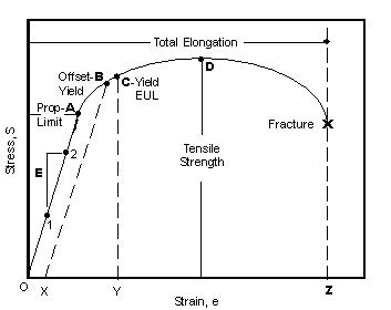
The results are generally displayed in a graphic representation, called the stress-strain diagram, where the strain (the percentage increase in dimension of a given "gage length") is measured along the horizontal x-axis, while the stress, equal to the load divided by the initial minimum cross section area, is measured along the vertical y-axis.
The strain is usually measured by an instrument called extensometer applied onto the specimen and connected to give the elongation corresponding to each stress value in sequence.
The deformation or strain so measured has significance as long as it is uniformly distributed, up to necking down: at that point the extensometer is usually disengaged and removed.
From the stress strain curve the following results are recorded:
The Ultimate Tensile Strength, the offset Yield Strength, usually measured by drawing a parallel to the initial portion of the diagram at 0.2% offset (line X-B in the figure).
The elongation at fracture is measured after rupture, by putting back to contact the two stumps of the broken specimen (in a suitable holder) and measuring the distance between the original marks of the gage length: the elongation is the difference (final - initial length) divided by the original gage length in percentage.
The reduction of area is again the difference (initial - final area at gage cross section) divided by the original area at cross section in percentage.
 |
Stress-Strain Diagram from
Measuring the Tensile Strength of Metals
See also:
Mechanical testing - Tensile testing, Part 1
TWI1.
Mechanical testing - Tensile testing Part II
TWI2.
An Article on Modern Non Contact Extensometers was published (7) in Issue 141 of Practical Welding Letter for May 2015.
Click on PWL#141 to see it.
An Article on Overview of modern Materials Testing Systems was published (7) in Issue 153 of Practical Welding Letter for May 2016.
Click on PWL#153.
Hardness Test
The hardness test is most useful in that it is generally non destructive, and can be performed with certain precautions even on finished parts (like gear teeth).
It describes the resistance to penetration of a specified indenter under specific load and special conditions.
An Article on Information from the Hardness Test was published (11) in Issue 146 of Practical Welding Letter for October 2015.
Click on PWL#146.
Creep Test
See our page on Creep Testand also the page on Creep Resistant Steels
Bend Test
See our page on Bend Testing.Impact Test
To determine the tendency of a material to behave in brittle manner, various types of notched bar impact tests are used.
The most common are called Charpy and Izod.
Brittle behavior of certain materials may strongly depend on temperature.
Click on PWL#072 to see it.
An Article on Testing Automotive Composites was published (3) in Issue 152 of Practical Welding Letter for April 2016.
Click on PWL#152.
An Article on Modern High Temperature Testing and another one on Induction Coupled Thermomagnetic Processing were published (11, 2) in Issue 155 of Practical Welding Letter for July 2016.
Click on PWL#155.
An Article on Third generation Advanced High-Strength Steel was published (2) in Issue 156 of Practical Welding Letter for August 2016.
Click on PWL#156.
See also:
ASTM E23 - Standard Test Methods for Notched Bar Impact Testing of Metallic Materials
BS-131-1 - Methods for Notched Bar Tests - Part 1: the Izod Impact Test on Metals
EN 10045 Part 1 Test Method
EN 10045 Part 2 Verification of Impact Testing Machines
Mechanical testing - notched bar or impact testing - Job Knowledge
TWI3.
Notched bar or impact testing. Part II - Job Knowledge
TWI4.
Watch the Video on
Mechanical Properties |
If you did not yet find what you need, why not typing your question in the following Search Box?
 Let us remind you that, if you are interested, we offer a no cost subscription to our Practical Welding Letter and a bonus book in pdf format to be made available for download to your computer on the subject of
PRACTICAL HARDNESS TESTING MADE SIMPLE. Click on Subscription.
To reach a Guide to the collection of the most important Articles from Past Issues of Practical Welding Letter, click on Welding Topics.
|
Note: To view Google Ads, Please Right Click and Open in a New Window. |
Back Home
Processes
Site Map
We used to remind to our readers titles and links to our informative pages on:
- welding basics,
- welding processes,
- welding materials and
- other welding related subjects.
We Were Just Trying to Make Ends Meet
Watch - The Video:
and also
POWERED BY:
Click on this Logo NOW!


